|
|
|
|
|
|
|
|
|
|
|
|
|
|
|
|
|
|
|
|
|
|
|
|
|
|
|
|
|
|
|
|
|
|
|
|
|
|
|
|
|
|
|
|
|
|
|
|
|
|
|
|
|
|
|
|
|
|
|
|
|
|
|
|
|
|
| |
|

|
|
|
Recommended
Print Settings:
Paper Size=Letter, Layout=Landscape, Margins=None, Scale=55%
|
M U L L I O N / A N C H O R C A P A C I T Y C A L C U L A T O R
|
FOR USE WITH
|
|
|
|
| |
|
|
|
|
NOA #20-0406.03
|
|
|
|
|
|
|
|
|
|
|
|
|
|
|
|
|
|
|
|
|
|
|
|
|
|
|
|
|
|
|
|
|
|
|
|
|
|
|
|
|
|
|
|
|
|
|
|
|
|
|
|
|
|
Mullion
|
Design
Pressure
(psf)
|
Anchor
Capacity
Required (lbs)
|
|
|
|
| |
|
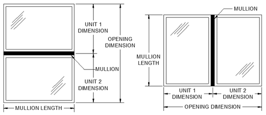
Enter Mullion Length:
|
|
in
|
|
|
|
|
|
|
|
|
|
|
|
|
|
|
|
| |
|
Enter Unit 1 Dimension:
|
|
in
|
|
|
|
|
|
|
|
|
|
|
|
|
|
|
|
| |
|
Enter Unit 2 Dimension:
|
|
in
|
|
|
|
|
|
|
|
|
|
|
1
|
1" x 2" x .125" Aluminum Tube
Mullion
|
|
|
|
|
|
| |
|
Unit 1
& 2 Dimensions should include half of your mullion thickness.
|
|
|
|
|
|
|
|
|
|
|
|
|
|
2
|
1" x 2" x .375" Aluminum Tube
Mullion
|
|
|
|
|
|
| |
|
|
|
|
|
|
|
|
|
|
|
|
|
|
3
|
1" x 2.75" x .375" Aluminum Tube
Mullion
|
|
|
|
|
|
| |
|
Your Opening
Dimension is:
|
|
in
|
|
|
|
|
|
|
|
|
|
|
|
|
4
|
1" x 2.75" x .650" Aluminum Tube
Mullion
|
|
|
|
|
|
| |
|
Use only the dimensions of 2 directly
adjacent units.
|
|
|
|
|
|
|
|
|
|
|
|
|
|
5
|
1" x 3.125" x .500" Aluminum
Tube Mull
|
|
|
|
|
|
| |
|
|
|
|
|
|
|
|
|
|
|
|
|
|
6
|
1" x 4" x .125" Aluminum Tube
Mullion
|
|
|
|
|
|
| |
|
Enter Loading Type (R or T):
|
|
R =
Rectangular, T = Trapezoidal/Triangular;
See "Load Areas" tab or approvals for examples. If unsure,
use Rectangular Loading.
|
|
7
|
1" x 4" x .375" Alum. Tube or
"T" Mullion
|
|
|
|
|
|
| |
|
The
Mullion Design Pressure for the dimensions given above are shown for each
mullion in the table on the right. Your selected mullion's Design Pressure
must meet or exceed the opening's required Design Pressure. Choose a specific
mullion, from the table at right, to determine the load transfered to the
Mullion Anchors. Your Anchor options will be given in the table below.
|
|
8
|
1.25" x 3.188" x .265" Aluminum
Tube Mull
|
|
|
|
|
|
| |
|
|
9
|
1.25" x 3.25" x .100" Aluminum
Tube Mull
|
|
|
|
|
|
| |
|
Enter Mullion Type (1-16):
|
|
Max. Design Pressure is:
|
|
psf
|
Load on Mullion Anchors is:
|
|
lbs
|
|
10
|
1.25" x 3.25" x .624" Aluminum
Tube Mull
|
|
|
|
|
|
| |
|
Knowing Your Anchor Load, you can now choose the
most appropriate anchor type from the table below.
|
|
|
|
11
|
1.25" x 3.94" x .624" Aluminum
Tube Mull
|
|
|
|
|
|
| |
|
|
Optional Design Pressure Reduction:
|
|
|
|
|
|
|
|
|
|
|
|
12
|
2" x 4" x .25" Aluminum Tube
Mullion
|
|
|
|
|
|
| |
|
|
|
If your Mullion's Design Pressure is much higher than what your
structure's opening actually requires, you may reduce the Mullion's Design
Pressure. This lowers the anchor capacity required and could give you
additional anchor options or require less anchors.
|
|
13
|
2" x 6" x .25" Aluminum Tube
Mullion
|
|
|
|
|
|
| |
|
|
|
|
14
|
1.26" x 2.11" x .125" Aluminum
Tube Mull
|
|
|
|
|
|
| |
|
|
Enter Reduced
Mullion Design Pressure:
|
|
psf
|
Your reduced
Anchor Capacity required is:
|
|
lbs
|
|
15
|
3.25" 30 Degree Aluminum Bay Mullion
|
|
|
|
|
|
| |
|
|
|
|
|
|
|
|
|
|
|
|
|
|
|
|
|
|
16
|
3.25" 45 Degree Aluminum Bay Mullion
|
|
|
|
|
|
| |
|
|
|
|
| |
|
Anchor Load
for :
|
Substrate:
|
2.7k
Concrete
|
3k Concrete
|
3.5k
Conc.
|
Hollow CMU
|
Filled
CMU
|
PT Wood
|
Metal
|
|
|
| |
|
|
Anchor Type:
|
3/16" Elco
Ultracon
|
1/4" Elco
Ultracon
|
3/16"
DeWalt
Ultracon+
|
1/4" DeWalt
Ultracon+
|
5/16" Elco
Ultracon
|
3/16"
Elco
Ultracon
|
1/4" Elco
Ultracon
|
3/16"
DeWalt
Ultracon+
|
1/4"
DeWalt
Ultracon+
|
1/4" SS Elco
Aggre-
Gator
|
5/16" Elco
Ultracon
|
1/4" SS Elco
Aggre-
Gator
|
#10
Steel
Screw (G5)
|
#12
Steel
Screw (G5)
|
#12
Steel
Screw (G5)
|
|
|
| |
|
All values in lbs
|
Edge Distance (in):
|
1"
|
2-1/2"
|
1"
|
2-1/2"
|
1"
|
2-1/2"
|
1"
|
2-1/2"
|
3-1/8"
|
1"
|
2-1/2"
|
1"
|
2-1/2"
|
1"
|
2-1/2"
|
1"
|
2-1/2"
|
2"
|
3-1/8"
|
2"
|
0.48"
|
0.54"
|
0.324"
|
|
|
| |
|
Embedment (in):
|
1-3/4"
|
1-3/4"
|
1-3/4"
|
1-3/4"
|
1-3/4"
|
1-3/4"
|
1-3/4"
|
1-3/4"
|
2"
|
1-1/4"
|
1-1/4"
|
1-1/4"
|
1-1/4"
|
1-1/4"
|
1-1/4"
|
1-1/4"
|
1-1/4"
|
1-1/4"
|
1-1/4"
|
2"
|
1-3/8"
|
1-3/8"
|
varies
|
|
|
| |
|
|
|
|
|
|
|
|
|
|
|
|
|
|
|
|
|
|
|
|
|
|
|
|
|
|
|
| |
|
|
|
|
|
|
|
|
|
|
|
|
|
|
|
|
|
|
|
|
|
|
|
|
|
|
|
| |
|
|
|
|
|
|
|
|
|
|
|
|
|
|
|
|
|
|
|
|
|
|
|
|
|
|
|
| |
|
|
|
|
|
|
|
|
|
|
|
|
|
|
|
|
|
|
|
|
|
|
|
|
|
|
|
| |
|
|
|
|
|
|
|
|
|
|
|
|
|
|
|
|
|
|
|
|
|
|
|
|
|
|
|
| |
|
|
|
|
|
|
|
|
|
|
|
|
|
|
|
|
|
|
|
|
|
|
|
|
|
|
|
| |
|
|
|
|
|
|
|
|
|
|
|
|
|
|
|
|
|
|
|
|
|
|
|
|
|
|
|
| |
|
|
|
|
|
|
|
|
|
|
|
|
|
|
|
|
|
|
|
|
|
|
|
|
|
|
|
| |
|
|
|
|
|
|
|
|
|
|
|
|
|
|
|
|
|
|
|
|
|
|
|
|
|
|
|
| |
|
|
|
|
|
|
|
|
|
|
|
|
|
|
|
|
|
|
|
|
|
|
|
|
|
|
|
| |
|
* Indicates
that the Clip & Anchor option does not meet the minimum capacity required
for the mullion's maximum Design Pressure. You may reduce the Design Pressure
from the optional section above. N/A indicates that the anchor's tested
spacing prohibits its use in this instance.
|
|
|
| |
|
For Clip Figures, see the Mullion NOA or Florida
Approval Drawing.
|
|
|
|
|
|
|
|
|
|
|
|
|
|
|
|
|